Induction sealing machinery products
Automatic inline induction foil sealing equipment for cap liners, bottles and jars. Each system should be selected around pack dimensions, liner specification, conveyor layout and required output.
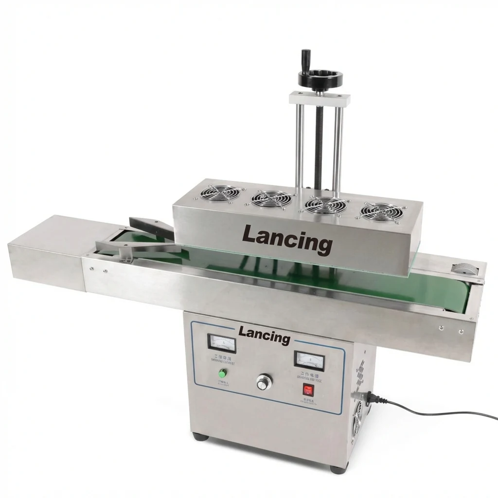
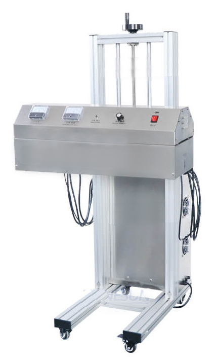
Automatic induction foil sealing machine
Air-cooled induction sealer with adjustable stand, induction head and controller for production-line sealing after capping.
- Common sealing head ranges from 15 mm to 130 mm
- Typical 220 V, 50 Hz, 4.2 kW reference unit
- Up to 260 bottles per minute depending on pack and setup
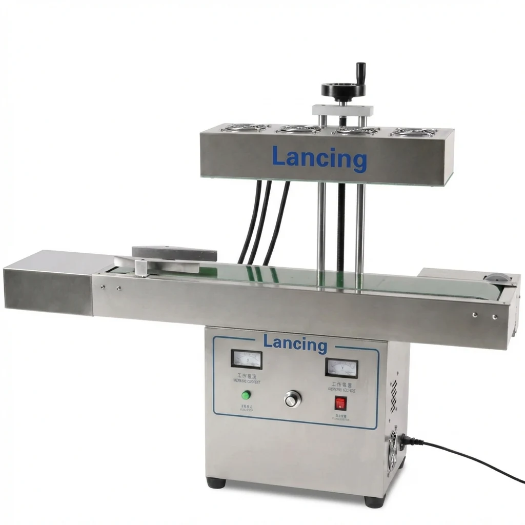
Head and cap range options
Specify the sealing head around cap diameter and pack geometry. Correct head selection helps avoid weak edges, overheating and inconsistent results.
- 15–60 mm
- 20–70 mm
- 35–85 mm
- 50–120 mm or 60–130 mm
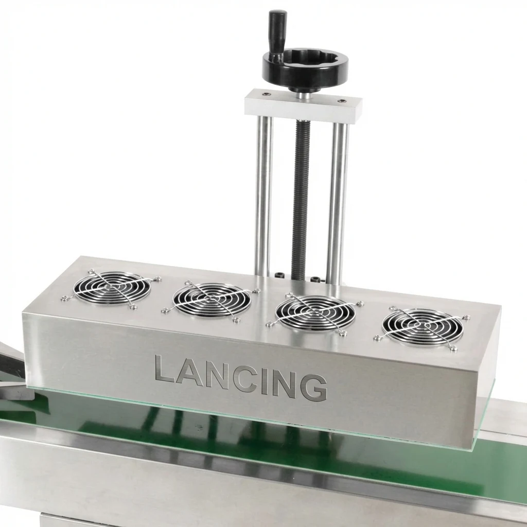
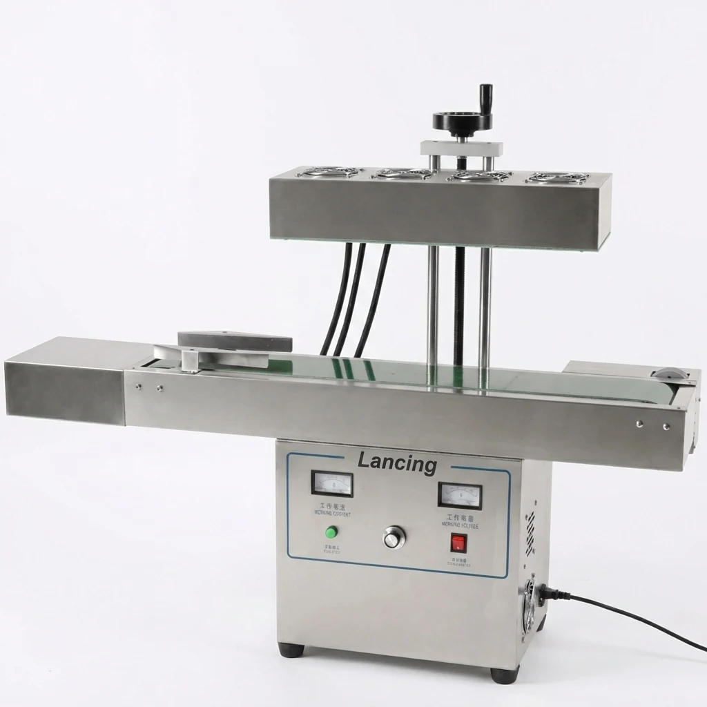
What to specify before choosing a model
The correct induction sealer depends on more than the machine power rating. The container mouth, liner construction, closure torque, conveyor speed, pack spacing and desired seal quality all need to work together.
- Cap diameter and sealing land width
- Foil liner supplier and material stack
- Plastic or glass container material
- Bottle or jar height range
- Target output and conveyor speed
- Available line space and conveyor height
Want the correct induction sealer specified?
Send sample details and your production target for a practical recommendation.
Choose the product route by cap range, sealing head and line role.
A continuous induction sealer should be selected after confirming the packaging components and the space available around the existing line. The machine range is not chosen by speed alone; the same target output can require different settings where the cap diameter, foil liner or product changes.
| Head diameter range | Use the smallest and largest cap or closure diameter on the line. The supplied range includes head options covering approximately 15–130 mm, but final coverage is model and application dependent. |
|---|---|
| Container material | PET, HDPE, PP and glass packs can all require different liner constructions. Confirm the liner is designed for the actual container material before testing the machine. |
| Line position | The sealer is normally placed after the capper, where the cap has already applied pressure to the liner, and before labelling, sleeving or final packing. |
| Selection next step | Send samples and line details using the induction sealer quote form, or read the quote checklist first. |
Select the induction sealing machine by head range and line role.
Use the product page as the commercial route, then check the technical guides before requesting a final recommendation. The right machine depends on the sealing head range, cap and liner compatibility, container height and how the sealer will be installed after the capper.
| Selection point | What to confirm before quotation |
|---|---|
| Cap and head range | Measure the cap outside diameter across the smallest and largest pack. The current model-dependent head ranges run across approximately 15–130 mm, but the correct head must be selected around the actual cap group. |
| Container material and liner | Confirm whether the heat-seal layer on the foil liner is intended for PET, HDPE, PP, glass or another material. The machine cannot make an incompatible liner bond reliably. |
| Line position | Most applications place the sealer after capping, with enough straight conveyor to keep the capped container stable under the induction head. |
| Acceptance checks | Plan peel checks, leak checks and retained setup samples where seal integrity is important for storage, transport or customer confidence. |
Use the product pages for different parts of the buying decision.
The pages below separate machine format, line role, cooling and the specific Lancing reference unit so buyers can reach the right level of detail.
| Page | Best used for | Next check |
|---|---|---|
| Automatic induction foil sealing machine | Reference specification, machine images, included scope and model-dependent ranges. | Confirm samples, head option and sealing-window acceptance. |
| Automatic induction sealers | Category-level comparison for bottle and jar production moving from manual to automated sealing. | Check operator involvement, output and line controls. |
| Inline induction sealers | Continuous operation after capping on a packaging conveyor. | Check capper, conveyor transfer, spacing and interlocks. |
| Air-cooled induction sealers | Cooling and installation considerations for the supplied air-cooled configuration. | Check ambient conditions, ventilation, duty and service access. |
Confirm the operating envelope, not only the nominal cap diameter.
The sealer must deliver an acceptable bond across the intended production range. That means proving the smallest and largest cap groups, normal and boundary conveyor speeds, representative product conditions and the cap-torque variation expected from the upstream process.
Where multiple products use the same diameter but different liner construction or container material, treat them as separate validation groups until evidence shows one setup can cover them.
- List every cap diameter and liner code.
- Group PET, HDPE, PP and glass packs separately.
- State normal, minimum and maximum production speeds.
- Measure conveyor height, width and available straight length.
- Define foil-presence, peel and leak checks.
- Identify required controls, rejection and documentation.
Questions that change the induction sealer specification
How is the correct induction sealing head chosen?
The sealing head is chosen from the cap and foil geometry, not from the machine power alone. Lancing needs the cap outside diameter, closure profile, foil position inside the cap, container height and the range of packs that must run. The proposed head must direct an effective induction field into each liner while allowing stable passage beneath it. See how to choose an induction sealing head.
Can one head cover both small bottles and wide-mouth jars?
Sometimes, but it should not be assumed. A head may cover a useful diameter range, yet a wide-mouth closure and a small cap can place very different demands on field distribution, foil position and changeover settings. The pack range should be grouped and trialled before deciding whether one head is sufficient. The wide-mouth sealing guide explains the additional checks.
Does a higher power rating always produce a better seal?
No. Seal quality comes from the correct relationship between power, exposure time, head position, cap pressure and liner compatibility. Excess energy can overheat or distort components, while too little energy can leave weak or incomplete bonding. Compare machines by the proven pack range, controllability, duty and integration scope rather than treating the highest power number as the deciding factor.
When should an air-cooled or water-cooled system be considered?
Choose the cooling architecture from the required duty, production environment, utilities and maintenance plan. The supplied Lancing range is air cooled, which can simplify installation by avoiding an external water circuit. A different cooling approach may be evaluated for another machine or unusually demanding environment, but it does not remove the need to prove the cap, liner and container. Compare the trade-offs in the air-cooled versus water-cooled guide.
Shortlist the machine family by the evidence the line must produce.
The product page should lead the buyer to the correct engineering conversation: pack compatibility, line integration and acceptance evidence. A simple manual or semi-automatic sealing operation may be adequate for low volumes, but a continuous inline induction sealer is normally selected when sealing must sit after capping and before labelling, coding, inspection or packing.
Before comparing automatic induction sealers, group the SKUs by cap diameter, cap profile, container material and liner supplier. If one group requires a different sealing head or a separate setup sheet, that should be visible in the quotation rather than discovered during commissioning.
| Product-search term | Underlying buyer task | Useful page |
|---|---|---|
| Automatic induction sealer | Continuous machine selection for bottles and jars after capping. | Automatic induction sealers |
| Continuous induction sealer | Line-speed, conveyor and hand-off planning. | Inline induction sealers |
| Cap induction sealer | Closure, liner and neck-finish compatibility. | Cap and liner sample trial plan |
| Foil sealing machine | Seal validation and acceptance evidence. | FAT/SAT acceptance plan |
Specify the induction sealing station around the hidden line decisions.
Two induction sealers can look similar in photographs but differ in the parts of the project that decide whether the final line is stable: sealing-head route, cap and liner grouping, missing-foil detection, reject handling, chemical risk review and the way leakage complaints will be tested.
Use these additional product-selection routes when the basic automatic or inline machine page does not answer the full application.