Automatic induction foil sealing machine
Air-cooled inline induction sealer for tamper-evident aluminium foil liner seals on bottles and jars. Stainless construction, straightforward setup and production-line integration.
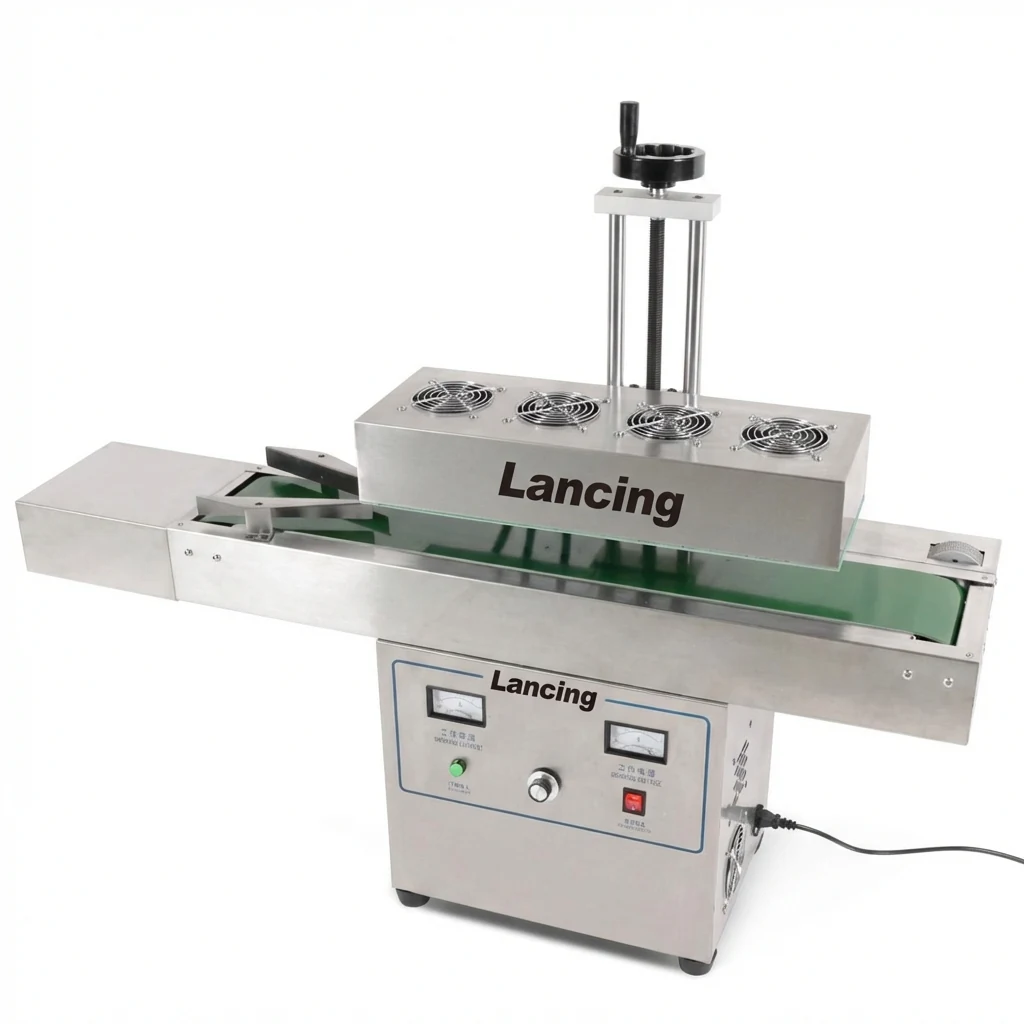
Automatic inline induction foil sealing machine for capped containers.
Reliable non-contact sealing after capping.
This machine transmits a high-frequency magnetic field to the induction sealing head. The aluminium foil at the bottle mouth is electromagnetically induced to generate heat. When the sealing layer reaches the correct temperature it melts and bonds to the container mouth, producing an efficient, high-quality foil seal.
Consistent tamper evidence
Helps protect products and reassure customers that the container has not been opened.
Inline configuration
Positioned after the capping process with adjustable head height for production-line use.
Air cooled design
Practical for many production environments without an external water-cooling circuit.
Technical specifications
| Power supply | 220 V, 50 Hz |
|---|---|
| Power | Approx. 4200 W on the reference unit |
| Sealing diameter | 15–60 mm, 20–70 mm, 35–85 mm, 50–120 mm or 60–130 mm depending on head option |
| Sealing speed | 0–260 bottles/minute, subject to bottle size, cap, liner and line conditions |
| Suitable bottle height | Approx. 10–300 mm based on a 900 mm conveyor height |
| Machine size | Approx. 700 × 690 × 1450 mm, model dependent |
| Cooling | Air cooled |
| Body | Stainless steel construction |
What is included?
- Induction sealing head and controller
- Adjustable stand
- Operation manual
- Application support from Lancing UK
Machine image gallery
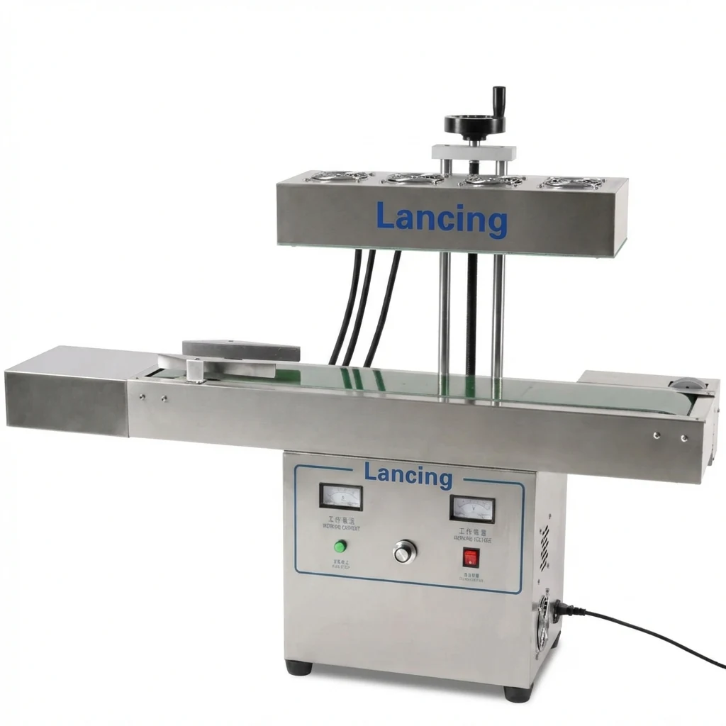
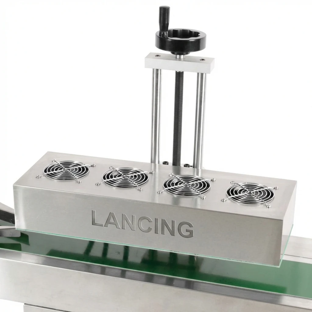
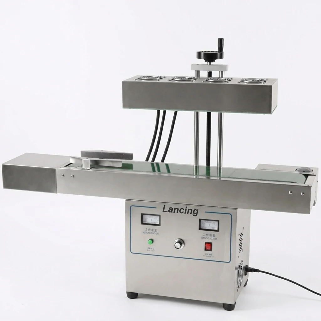
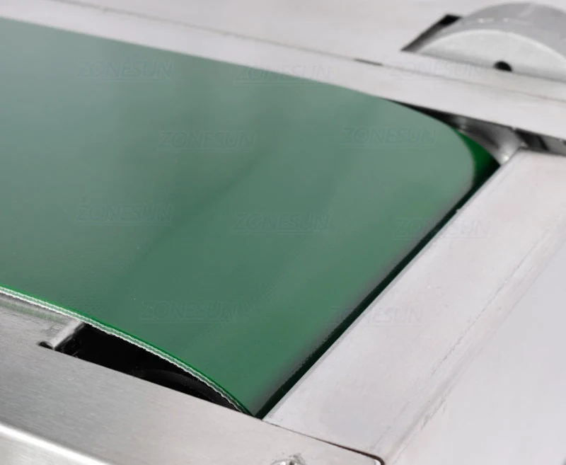
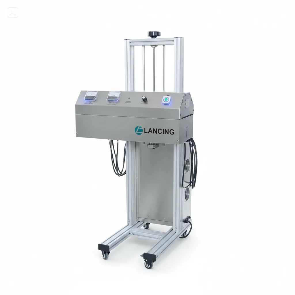
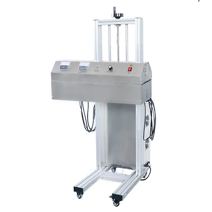
Supplied product images showing the inline sealer, sealing head, conveyor and floor-standing induction sealing options.
Check compatibility before ordering.
Send your bottle, cap and liner details. Lancing UK can confirm the best sealing diameter range and line setup.
Model-dependent ranges and sealing-window checks.
The specification below should be used as a project starting point. Final settings and head selection depend on the actual cap, liner, container material, neck finish, bottle spacing and conveyor conditions tested with production samples.
| Verified reference range | Head options cover approximately 15–60 mm, 20–70 mm, 35–85 mm, 50–120 mm and 60–130 mm depending on the selected sealing head. |
|---|---|
| Speed reference | The reference speed is up to 260 containers per minute, but practical output must be confirmed under sample-trial conditions with the intended cap diameter, foil liner, product and conveyor speed. |
| Power and dwell time | A higher conveyor speed reduces dwell time under the induction field. Settings should be recorded against each cap and liner combination rather than copied between different packs. |
| Cap torque | Torque should be consistent enough to hold the liner evenly against the container mouth. Too little pressure can cause incomplete bonding; excessive torque can distort some packs. |
| Validation route | Use visual checks with peel testing and leak testing on retained samples from the lowest, target and highest intended line speeds. |
From induction field to bonded foil liner.
The capped container passes under the induction sealing head. The field heats the aluminium layer of the foil liner without the head touching the cap. Once the heat-seal layer reaches its working temperature, it bonds to the container mouth. The machine therefore needs the right relationship between power setting, conveyor speed, sealing-head height, cap torque and liner construction.
For a new project, send Lancing UK the complete cap and liner information, container samples and target output. Where there are several SKUs, group them by cap diameter and material so the practical changeover workload can be assessed before quotation.
| Good starting evidence | Cap drawings, liner specification, container material, photographs, filled product details and current line speed. |
|---|---|
| Trial result to keep | Accepted power/speed/head-height setting, cap torque range, date, operator, sample batch and any rejected settings. |
| When another route may be needed | If the closure cannot hold the liner, the container mouth is uneven, the liner is not suitable or the pack is outside the head range. |
Buyer FAQs for the automatic induction foil sealing machine
Can one induction sealer run several cap sizes?
It may be possible when the selected sealing head covers the cap range and each liner/container combination has a proven setting. Very different diameters may require a different head or separate setup record.
Is the up to 260 containers per minute figure guaranteed on every pack?
No. It is a model-dependent reference and must be confirmed against the actual cap diameter, liner, container, product, bottle spacing and conveyor speed.
Does induction sealing need cap torque control?
Consistent cap application is important because the cap holds the foil liner against the container mouth during sealing. The sealer cannot correct a badly applied cap.
Can the machine be placed after an existing capper?
Yes, that is the normal line position, provided there is enough conveyor space, stable bottle transfer, compatible conveyor height and access for adjustment.
What should be tested before sign-off?
Use sample packs to confirm visual seal quality, peel behaviour and leak performance across the intended operating range. Keep accepted settings for repeatability.
What information does Lancing need for quotation?
Send cap diameter, liner type, container material, bottle height, target output, conveyor details, utilities and photos or samples where available.
Record test conditions for every diameter and speed reference.
The headline ranges on this page are useful for shortlisting, but production suitability should be confirmed against the actual components. Treat diameter and speed as project variables to be proven, not as a universal guarantee across every bottle, jar, cap and liner.
| Area to record | Why it matters | How to check it |
|---|---|---|
| Cap outside diameter | Determines the sealing-head range and the heating area that must be covered. | Measure the smallest and largest cap in the intended SKU group and check they sit within the selected head range. |
| Foil liner construction | The aluminium layer heats, but the heat-seal layer creates the bond to the container mouth. | Ask the cap or liner supplier for the intended container material and keep a copy with the setup record. |
| Conveyor speed and dwell time | Higher speed reduces time under the induction field, so the practical output depends on power, spacing and pack stability. | Trial low, target and high speeds using filled or representative samples and retain accepted settings. |
| Cap torque and neck finish | The cap must hold the liner evenly on a clean, flat mouth until the seal bonds and cools. | Check cap application consistency, rim condition and any product contamination before blaming the sealer setting. |
| Reject or inspection route | Missing foils, skewed caps or unstable transfer can still create bad packs around a working sealer. | Agree whether the line needs operator inspection, foil detection, reject handling or a documented sampling routine. |
Before FAT or sample trial
Send cap samples, liner details, container material, bottle height, target containers per minute and photographs of the current line. Include the filled product where it affects leakage, cooling or handling.
During setup
Record power setting, conveyor speed, head height, cap torque guidance, result after cooling and whether each sample passed visual, peel and leak checks.
After commissioning
Keep a setup sheet for each cap and liner group so operators can return to an approved setting after changeover rather than re-finding it by trial and error.
Options and interfaces that can change the final induction sealing station.
The reference specification identifies the core machine. The final configuration depends on the pack range, existing conveyor and the level of inspection, control and project support required.
| Sealing head | Select around the real cap-diameter group and geometry. Widely different closures may require a different head or separate setup work. |
|---|---|
| Conveyor interface | Confirm belt or slat type, top-of-belt height, speed range, guides, available straight length and whether the existing conveyor can provide stable passage. |
| Bottle spacing | Pack gaps must support the intended dwell time and any downstream inspection or rejection logic. |
| Foil inspection | Define whether the project needs missing-foil detection, where it is measured and how a detected pack is tracked. |
| Reject handling | Specify reject device, collection, confirmation, full-bin or jam response and the test used to prove failed packs do not continue. |
| Controls | Agree local/remote operation, run permissives, fault signals, recipes, counters and the response to conveyor or capper stops. |
| Project services | State sample trials, drawings, FAT, installation, commissioning, training, setup records and aftercare required in the quotation. |
Prove the machine at representative production conditions.
Use the actual cap, liner, container and product. Test more than a single target setting so the operating margin is understood. An accepted result should show repeatable sealing at the intended cap torque and conveyor conditions, not only an isolated good sample.
Record the lower, target and upper trial conditions, allow the foil to cool before the agreed peel check, and retain samples where the buyer's quality process requires them.
- Confirm liner presence and cap application before adjusting the sealer.
- Align the head to the cap centre and record the head height.
- Test intended production speed and defined boundary conditions.
- Inspect the full seal circumference after cooling.
- Complete the agreed leak or handling check.
- Record accepted and rejected settings for each SKU group.
Commercial and installation guidance
Induction sealer cost factors
Compare the core sealer, conveyor, inspection, controls, trials and installation on a like-for-like basis.
Site preparation and utilities
Check electrical supply, line space, controls, access, samples and commissioning ownership.
Automatic induction sealers
Compare continuous bottle and jar sealing around cap range, repeatability, controls and validation.
Questions about running the automatic induction sealer on a production line
What happens if bottles are not centred beneath the sealing head?
Off-centre bottle presentation can expose the foil unevenly to the induction field and make results less repeatable. Guide rails, conveyor tracking, bottle spacing and the transfer from the capper should keep the closure on a stable path beneath the head. Where several bottle shapes run, record the guide and head settings for each format rather than relying on visual alignment alone. The line-integration guide covers the required hand-offs.
How should an automatic induction sealer respond to a conveyor stop?
The control philosophy should prevent a capped container from remaining under an energised head for an uncontrolled period. The exact interlock depends on the sealer, conveyor and wider line controls, so stop, restart, backup and fault conditions should be agreed before commissioning. Use representative packs to verify the behaviour and document who owns each interlock during the acceptance test.
Can the sealing head height be changed between SKUs?
Yes, where the machine's adjustment range accommodates the containers, but the setting must be controlled. Bottle height, cap profile and the foil's position within the closure affect the working gap. Record the approved head height with the power and conveyor setting for each SKU, then recheck seal quality after changeover. The sealing-window setup sheet provides a useful record structure.
Can this automatic induction sealer be used with metal caps?
A conventional through-cap induction application should not be assumed suitable for a metal closure. The closure itself can interact with the induction field and change the heating pattern. If a metal cap is essential, review the whole closure system and consider whether a separate membrane-sealing process is more appropriate. See the dedicated guide on induction sealing and metal caps before sending samples.
Convert the reference specification into an acceptance-ready machine scope.
The published head ranges and speed reference are shortlisting information; the purchase decision should be based on tested pack conditions. The same machine can behave differently when cap diameter, foil liner, product residue, container mouth, cap torque or conveyor speed changes. For this reason, Lancing should be given the actual pack components and the intended operating window before the quotation is locked.
A robust project scope identifies what the machine must prove at trial, what the buyer will check on site and which downstream actions are required if a bottle has no liner, a high cap, a poor seal or unstable transfer. That avoids comparing only the base sealer and missing the controls, detection or conveyor details that make the line usable.
| Scope item | What should be confirmed before order |
|---|---|
| Pack families | Smallest, largest, tallest and most difficult cap/container combinations. |
| Sealing head | Selected against closure diameter, foil position, container path and pack geometry. |
| Operating setting | Power, conveyor speed, bottle spacing, head height and cooling interval for each accepted format. |
| Acceptance evidence | Visual seal, peel behaviour, leak or handling check, retained samples and documented rejected settings. |
| Line response | Stop/restart logic, fault signals, missing-foil response, reject route and operator intervention. |
Use optional checks to turn a machine enquiry into a line-ready specification.
The reference machine page covers the core inline induction sealer. These additional checks help decide whether the quoted station also needs specific head geometry, detection, reject handling, transit evidence or chemical-product review.
| Buyer risk | What to check | Best next page |
|---|---|---|
| Mixed cap geometry | Compare flat/tunnel head routes and decide whether one head can cover every group. | Flat vs tunnel heads |
| Unsealed packs reaching downstream operations | Define missing-foil detection, high-cap checks, reject tracking and proof tests. | Detection and rejects |
| Courier or ecommerce leakage | Test the pack in the orientation and handling condition that creates the real complaint. | Transit leak control |
| Solvent or flammable chemical product | Review SDS, DSEAR/site classification, ventilation and safe trial method before assuming suitability. | Chemical checks |